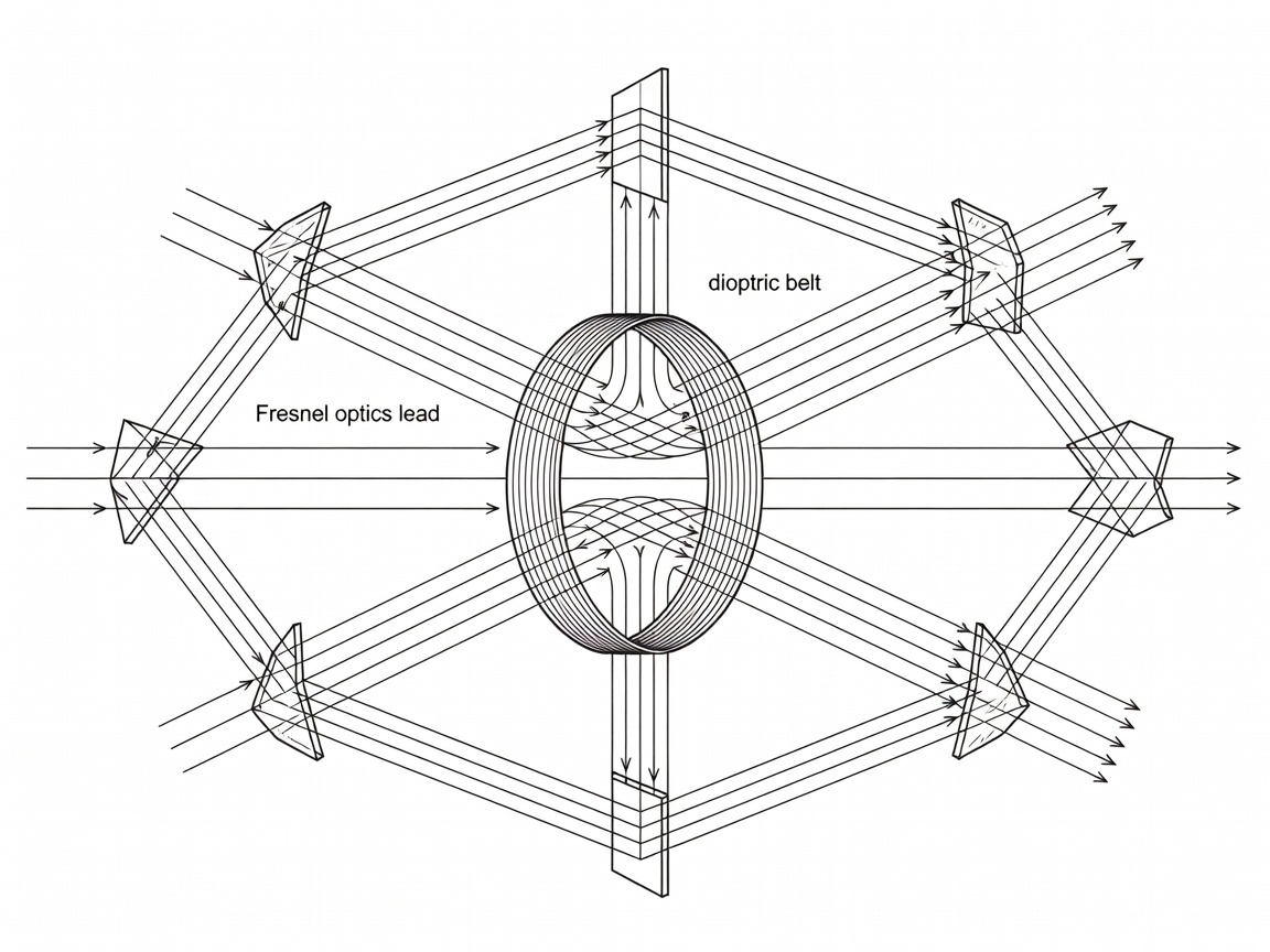
The Catoptric to Dioptric Revolution
Prior to 1820, marine aids to navigation relied on catoptric systems: silver-plated parabolic reflectors positioned behind oil burners. These systems suffered from severe photometric limitations. Even with polished metal surfaces, parabolic mirrors absorbed between 40% and 50% of emitted luminous flux. Beam concentration was poor, scattering light upward into the atmosphere or down into coastal surf where it had zero utility for mariners.
Augustin-Jean Fresnel’s stepped lens transformed lighthouse optics. By breaking a solid spherical lens into concentric annular rings supported in brass frameworks, Fresnel eliminated the bulk and weight of thick glass while maintaining a short focal length. A central bullseye panel refracts divergent light rays into a parallel beam (the dioptric action). Above and below this central belt, triangular glass prisms bend and reflect light via total internal reflection (the catadioptric action). The composite apparatus captures up to 80% of an open flame’s emitted light, concentrating it into tight horizontal beams visible beyond the geometric horizon.
The Optical Orders and Stevenson Innovations
Lighthouse lenses are categorised into standardised optical "orders" based on their internal focal distance (the radius from the light source to the inner lens face). In Britain and Ireland, Thomas Stevenson and Alan Stevenson championed variations to Fresnel’s continental specifications, culminating in the holophotal lens, which completely encapsulates the light source with zero wasted peripheral spill.
| Optical Order Classification | Internal Focal Radius | Apparatus Height | Typical Operational Site |
|---|---|---|---|
| Hyper-radial | 1,330 mm | Up to 4.5 metres | Bishop Rock, South Stack, Bull Rock |
| First Order | 920 mm | Approx. 2.6 metres | Fastnet, Skerryvore, Bell Rock |
| Second Order | 700 mm | Approx. 2.0 metres | Outer Skerries, Calf of Man |
| Third Order | 500 mm | Approx. 1.6 metres | Estuary & Headland Primary Stations |
| Fourth to Sixth Order | 300 mm down to 150 mm | Under 1.0 metre | Harbour entrances, pierheads, river reaches |
The Hyper-Radial Order: Giant Glass of the Atlantic Seaboard
As burner technology progressed from simple argand lamps to multi-wick Trinity House oil lamps and Arthur Kitson’s vaporised incandescent paraffin mantle burners, flame volume increased dramatically. Standard First Order optics could not accommodate the expanded physical mantle diameter without suffering focal dispersion and beam divergence. Thomas Stevenson proposed an optical order exceeding First Order dimensions: the Hyper-radial apparatus.
Manufactured primarily by Chance Brothers of Smethwick, Birmingham, and Barbier, Bénard & Turenne in Paris, these hyper-radial lenses remain some of the largest optical instruments ever cast. Weighting between 5 and 12 tonnes, an entire revolving hyper-radial assembly could not rotate smoothly on mechanical rollers without severe bearing wear and erratic rotational timing.
Liquid Mercury Trough Flotation
In 1892, French engineer Bourdelles resolved the bearing friction bottleneck by floating the entire optic frame in an annular ring filled with liquid mercury. By displacing its own weight in a bath of dense metallic mercury, an optic assembly weighing 6 tonnes could be rotated with the push of a finger.
Clockwork drives governed by weighted falling pendulums and mechanical escapements were deployed to maintain exact angular velocity. A steady drop of a heavy cable weight inside the hollow core of the tower drove the mercury bath gears continuously through the night watch, generating flash sequences accurate to within tenths of a second.